Our products and installations are approved for and in compliance with:
NYC LL 26 (New York City Local Law 26)
NYC LL 141 (New York City Local Law 141)
UL 1994
UL 924
IBC (International Building Code)
IFC (International Fire Code)
Door Signs
Steps
Landings
Handrails
Floor perimeter demarcation lines
Obstacles
Directional signage upon entering an exit
Directional Signage at transfer levels and where egress direction is not clear
“Not an Exit” sign
Intermediate exit doors and final exit doors
Door Signs
Door Hardware markings
Door Frame markings
General standards
Door Signs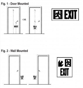
fig_2
Fig. 1 – Door Mounted
Fig. 2 – Wall Mounted
New Buildings:
The top of the signs shall be no higher than 18” above the finished floor. Signs shall be installed either on the door itself, or on the wall surface directly adjacent to the door, or both:
2.1.1.1 Door Mounted Option (fig. 1).
The vertical centerline of the sign shall be centered with the door, or shall be in that half of the door, either the right or left, that contains the latch. In case of double-doors, both doors shall be marked and the signs shall be centered with the doors. For door-mounted signs, arrows may be omitted.
2.1.1.2 Wall Mounted Option (fig. 2).
Signs shall be mounted on the wall surface directly adjacent to the latch-side of the door, no more than 6” from the door to the edge of the sign. In case of double-doors, signs shall be placed on the wall surface directly adjacent to the hinge- sides of both doors. Where the wall surface directly adjacent to the latch-side is too narrow to accommodate the sign, the sign may be placed on the adjacent perpendicular wall. For wall-mounted signs, arrows are mandatory.
Existing Buildings (approved prior to July 1, 2006):
Top of sign to be no higher than 26” above the floor.
Steps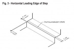
fig_3
Fig. 3 – Horizontal Leading Edge of Step
New Buildings:
Step markings (fig. 3)
The entire horizontal leading edge of each step shall be marked with a solid and continuous stripe of photoluminescent material. 2.2.1.1 Width: The width of the strips shall be: Max 2”, Min 1” 2.2.1.2 Length: The stripes shall extend for the full length of the step. 2.2.1.3 Placement: The leading edge of the stripe shall be: Max 1/2 “ Min 0” from the leading edge of the step. 2.2.1.4 Overlap: the stripe shall not overlap the leading edge of the step by more than 1/2 “ down the vertical face of the step.
Existing Buildings (approved prior to July 1, 2006):
In lieu of marking the full horizontal leading edge, compy with one of:
1) Step markings (fig. 3)
The entire horizontal leading edge of each step shall be marked with a solid and continuous stripe of photoluminescent material. 1.1 Width: Same 1.2 Length: Shall extend to within 2” of both sides of the steps. 1.3 Placement: The leading eadge of t he stripe shall be: Max 1“ Min 0” from the leading edge of the step. 2.2.1.4 Overlap: Same
OR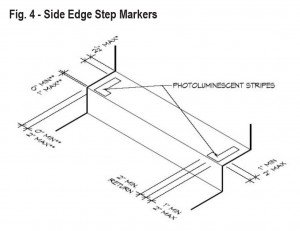
fig_4
Fig. 4 – Side Edge Step Markers
New Buildings:
2) Side Edge Markings.
Not permitted.
Existing Buildings (approved prior to July 1, 2006):
2) Side edge markings (fig. 4)
Side edge markings on both horizontal sides of each step that provide returns extending along the leading edge. Shall be solid and continuous stripes of photoluminescent material: 2.1 Width of side edge markings. Same as 2.2.1.1 2.2 Placement of side edge markings. No further than 2” from both sides of steps. Shall extend to within 21/ of each step and to within 1” of the leading edge of each step. 2.3 Width of returns. Shall also comply with 2.2.1.1 but are not required to be the same width as the side edge markings. 2.4 Placement of returns. Shall extend from the side edge marking, parallel with the leading edge of the step, for a minimum distance of 2”. Shall extend to within 1” of the leading edge of each step. 2.5 Overlap. The side edge markings including returns shall not overlap the face of the leading edge ofthe step by more than 1/2″ down the vertical face of the step. 4″ of the back 3.
Landings (leading edge)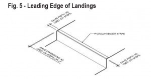
fig_5
Fig. 5 – Leading Edge of Landings
The leading edge of all landings shall be marked in a consistent and uniform manner throughout the same exit. Such markings shall comprise stripes following the same requirements as for steps in 2.2.1, except that: 1) the stripe shall be the same length as and consistent with the stripes on the steps, or may extend the full length of the leading edge of the landing; and 2) the leading edge of each landing shall be marked regardless of the age of the building.
Handrails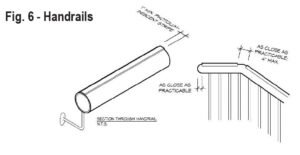
fig_6
Fig. 6 – Handrails
New Buildings:
All handrails and handrail extensions shall be marked with a solid and continuous stripe of photoluminescent material. 2.2.3.1 Width. Shall be Min. 1” 2.2.3.2 Placement. Shall be placed at least on the top surface of the handrail for the entire length of any handrails including handrail extensions, and newel post caps. 2.2.3.3 Continuity. Where handrails or handrail extensions bend or turn corners, the stripe shall be as continuous as practicable with no more than a 4” gap.
Existing Buildings (approved prior to July 1, 2006):
Handrails are not required to be marked.
Floor perimeter demarcation lines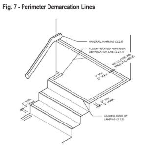
fig_7
Fig. 7 – Perimeter Demarcation Lines
Perimeter demarcation lines are intended to outline the egress path by providing low location photoluminescent lines on both sides of the path. Width: Min. 1”, Max. 2” Continuity: The continuity of the demarcation lines may be interrupted to accommodate obstructions such as conduits, moldings, corners or bends, not to exceed 4”. Shall be uniform and consistent throughout the same exit.
2.2.4.1 Floor-mounted option (fig. 7).
Shall be placed as close as practicable to the wall, and shall extend to within 2” of the landings’ leading edge markings. Where an obstruction (such as a standpipe) is located within the egress path, the demarcation line may, at the option of the owner, extend across the floor so that the obstruction is outside of the outlined area (see fig. 8). Demarcation lines on floors shall continue across the floor in front of all doors, except in front of those doors marked with door frame markings in accordance with 2.2.9.3 (see figs. 13, 14).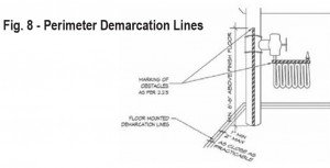
fig_8
Fig. 8 – Perimeter Demarcation Lines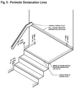
fig_9
Fig. 9 – Perimeter Demarcation Lines
2.2.4.2 Wall Mounted Option (fig. 9)
Shall be placed with the bottom edge no more than 4” above the finished floor. At the top or bottom of stairs, demarcation lines shall drop vertically to the floor within 2” of the step or landing edge. Demarcation lines on walls shall transition vertically to the floor and then extend across the floor where a line on the floor is the only practical method of outlining the path, for instance where obstructions or dead ends are to be outside of the outlined egress areas. Demarcation lines on walls shall continue across the face of all doors, or may transition to the floor and extend across the floor in front of such doors (see fig. 10), except in front of those doors marked with door frame markings in accordance with 2.2.9.3. EXCEPTIONS: Perimeter demarcation lines are not required: 1. on the sides of steps; and 2. where an area is selected not to be outlined because it is not part of the egress path, for example and obstruction or dead end.
fig_10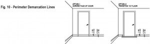
Fig. 10 – Perimeter Demarcation Lines
Obstacles
Obstacles at or below 6’-6” (1981mm) in height and projecting more than 4” (120mm) into the egress path shall be outlined with markings. Width: Min 1” Pattern: Alternating equal bands, of photoluminescent material and black, with alternating bands no more than 2” thick and angled at 45 degrees. Examples of such obstacles include standpipes, hose cabinets, wall projections, and restricted height areas (see fig. 8).
Directional Signage upon entering an exit (see fig. 11)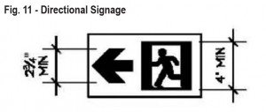
fig_11
Fig. 11 – Directional Signage
New Buildings:
Photoluminescent directional signs shall be placed in the stairwell or exit at every entrance thereto such that they are visible upon opening the door into the stairwell to exit (i.e. the opened door shall not obscure the sign). Such directional sign shall include an arrow indicating the direction of travel. The signs shall be located such that their top edge is no more than 18” above the finished floor.
Existing Buildings (approved prior to July 1, 2006):
Applies only to below grade stories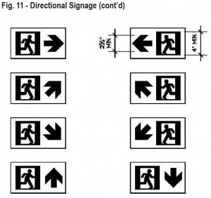
Directional Signage at transfer levels and where egress direction is not clear (see fig. 11)
fig_11_ctd
Fig. 11 – Directional Signage (cont’d)
Photoluminescent directional signs installed at heights indicated in 2.2.6 shall be placed on the wall: 1) at transfer levels; and 2) wherever egress direction is not clear. These directional signs shall include arrows indicating the direction of travel. Examples of placement include: at turns along horizontal extensions from vertical to horizontal direction; at a “T” intersection; etc. Arrows must be min 23/4 “ square, Running Man must be min. 4” square.
“Not An Exit” sign (see fig. 12)
Photoluminescent signs shall be placed on doors along the egress path that lead to dead ends (mechanical rooms, storage closets, etc.) Such signs shall contain sans serif lettering at least 1” high reading “NOT AN EXIT”.
Existing Buildings (approved prior to July 1, 2006):
Exempt from this requirement.
Intermediate exit doors and final exit doors
Definitions: Intermediate exit door (see fig. 13). When travelling in the egress direction, doors that lead from a vertical exit, horizontal extension in a vertical exit, horizontal exit, supplemental vertical exit, or exit passageway, but do not lead directly to the exterior or to a street level lobby are intermediate exit doors. Final exit door (see fig. 14). Doors leading to the exterior or a street level lobby are final exit doors.
fig_13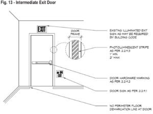
Fig. 13 – Intermediate Exit Door
fig_14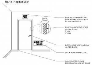
Fig. 14 – Final Exit Door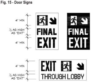
Door Signs
fig_15
Fig. 15 – Door Signs
A photoluminescent wall-mounted door sign complying with 2.1.1.2 shall be mounted on the wall adjacent to all intermediate and final exit doors. At the final exit door, such sign shall contain supplemental directional text in sans serif letters one-half as high as the word EXIT. The word EXIT must be 4” min. Examples of such texts are “FINAL EXIT”, or “EXIT THROUGH LOBBY” or “EXIT TO STREET”, or “EXIT TO CHAMBERS STREET”, etc (see fig. 15)
Door Hardware markings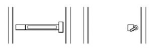
door_hardware_markings
Door hardware of all intermediate and final exit doors shall be marked with no less than 16”2 of photoluminescent material. This marking shall be located behind, immediately adjacent to, or on the door handle. Where a panic bar is installed, such material shall be no less than 1” wide for the entire length of the actuating bar or touchpad. All hardware markings covered by 2.2.9.2 may include ANSI Z535.1 safety green graphics such as arrows indicating door handle turning directions, E001 or E002 emergency egress symbols as per ISO 7010, the word “EXIT”, the word “PUSH”, and similar egress-related symbols provided the minimum 16”2 photoluminescent material is maintained.
Door Frame markings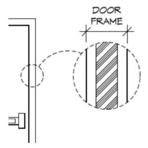
door_frame_markings
The top and sides of the door frame of all intermediate and final exit doors shall be marked with a solid and continuous 1” to 2” wide stripe of photoluminescent material. Gaps are permitted in the continuity of door frame markings where a line is fitted into a corner or bend, but shall be as small as practicable and in no case greater than 1”. Where the door molding does not provide enough flat surface on which to locate the stripe, the stripes may be located on the wall surrounding the frame. The dimensions, distances and locations fo the required markings shall be consistent and uniform on all doors on the route to the exterior of the building.
General standards
2.3.1 Design of door and directional signs.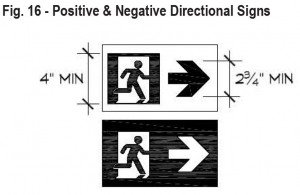
fig_16
Fig. 16 – Positive & Negative Directional Signs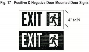
fig_17
Fig. 17 – Positive & Negative Door-Mounted Door Signs
Unless otherwise specified, all photoluminescent door signs and directional signs referenced herein (see figs. 11, 15, 16, 17): 1. may be either positive or negative image; 2. shall be made with the non-photoluminescent portions of the signs in safety green as per ANSI Z535.1-2002, American National Standard for Safety Color Code; 3. Shall include three components: 3.1 the word EXIT printed in sans serif letters at least 4” high with strokes no less than 1/2 “; 3.2 an emergency exit symbol at least 4” high, complying with E001 or E002 as per ISO 7010 (2003-10-01), Graphical Symbols – Safety Colours and Safety Signs – Safety Signs Used in Workplaces and Public Areas; and 3.3 an arrow at least 23/4 “ high, complying with E005 or E006 as per ISO 7010.
EXCEPTIONS:
1. Arrows are not mandatory on door-mounted signs required by 2.1.1.1
2. The word EXIT is not mandatory on directional signs required by 2.2.6 and 2.2.7
3. Additional descriptive text is permitted, provided such words are in sans serif letters and, where the word EXIT or emergency exit symbol is requried on such sign, such descriptive text is no more than one-half as high as the word EXIT or the emergency exit symbol.
Photoluminescent
Egress Marking
Standards
NYC Local Law compliance standards for photoluminescent safety markings in egress paths, stairwells, and exit routes.
Door & Wall Mounted
Door Mounted Option
The vertical centerline of the sign shall be centered with the door, or in the half containing the latch. For double-doors, both doors shall be marked and signs centered on each door.
| Max Height | 18" above finished floor (top of sign) |
Wall Mounted
Wall Mounted Option
Mounted on wall directly adjacent to latch-side, no more than 6" from door edge to sign edge. For double-doors, signs go adjacent to hinge-sides of both doors. If latch-side wall is too narrow, sign may go on the adjacent perpendicular wall.
| Max Height | 18" above finished floor (top of sign) |
Height Exception
Top of sign to be no higher than 26" above the floor.
Horizontal Leading Edge
Horizontal Leading Edge Stripe
The entire horizontal leading edge of each step shall be marked with a solid and continuous stripe of photoluminescent material.
| Width | Min 1" — Max 2" |
| Length | Full length of the step |
| Placement | Min 0" — Max ½" from the leading edge of the step |
| Overlap | No more than ½" down the vertical face of the step |
Modified Leading Edge
Modified Horizontal Leading Edge
| Width | Same as new buildings |
| Length | Within 2" of both sides of step |
| Placement | Min 0" — Max 1" from leading edge |
| Overlap | Same as new buildings |
Side Edge Markers
Side Edge Markings
Solid and continuous photoluminescent stripes on both horizontal sides of each step with returns extending along the leading edge.
| Side Width | Same as 2.2.1.1 |
| Placement | No further than 2" from both sides |
| Returns | Min 2" parallel to leading edge; within 1" of leading edge |
| Overlap | Max ½" down the vertical face |
Leading Edge of Landings
The leading edge of all landings shall be marked consistently and uniformly throughout the same exit, following the same stripe requirements as steps (2.2.1).
| Length | Same as stair stripes, or may extend the full length of the landing's leading edge |
| Applicability | Required regardless of building age — no exemption for existing buildings |
Handrails
All Handrails & Extensions
All handrails, handrail extensions, and newel post caps shall be marked with a solid and continuous stripe of photoluminescent material.
| Width | Min 1" |
| Placement | At least on the top surface for the entire length, including handrail extensions and newel post caps |
| Continuity | No more than 4" gap at bends or corners |
General Requirements
Outlines the egress path using low-location photoluminescent lines on both sides of the path.
| Width | Min 1" — Max 2" |
| Continuity | Max 4" gap to accommodate conduits, moldings, corners, or bends |
| Consistency | Uniform and consistent throughout the same exit |
Floor Mounted
Floor Mounted Demarcation
Placed as close as practicable to the wall. Extends within 2" of landing leading-edge markings. Continues across the floor in front of all doors (except those with door frame markings per 2.2.9.3). May route around obstructions such as standpipes so the obstruction is outside the outlined area.
Routing Around Obstruction
Floor Mounted — Obstruction Detail
Where an obstruction such as a standpipe is located within the egress path, the demarcation line may extend across the floor so that the obstruction is outside of the outlined area.
Wall Mounted
Wall Mounted Demarcation
Bottom edge no more than 4" above finished floor. At top or bottom of stairs, drops vertically to floor within 2" of step/landing edge. Continues across the face of all doors or transitions to the floor in front of such doors. May transition to floor where wall-mounting is impractical.
Transition to Floor
Wall to Floor Transition
Demarcation lines on walls shall transition vertically to the floor and then extend across the floor where a line on the floor is the only practical method of outlining the egress path.
2. Where an area is not part of the egress path (e.g., obstructions or dead ends).
All obstacles at or below 6'–6" (1981mm) in height and projecting more than 4" (120mm) into the egress path shall be outlined with markings (see Fig. 8).
| Width | Min 1" |
| Pattern | Alternating equal bands of photoluminescent material and black — max 2" thick, angled at 45° |
| Examples | Standpipes, hose cabinets, wall projections, restricted height areas |
Directional Signage
Stairwell Entrance Signs
Placed at every entrance to a stairwell/exit, visible upon opening the door — the open door must not obscure the sign. Includes an arrow indicating direction of travel.
| Max Height | Top edge no more than 18" above finished floor |
Transfer Levels
Transfer Level & Unclear Egress Signs
Placed on the wall at transfer levels and wherever egress direction is not clear — at turns along horizontal extensions, T-intersections, or direction changes from vertical to horizontal. Includes arrows indicating direction of travel.
| Arrow | Min 2¾" square |
| Running Man | Min 4" square |
Photoluminescent signs placed on doors along the egress path that lead to dead ends such as mechanical rooms, storage closets, and similar spaces.
| Text | Sans-serif lettering, min 1" high, reading "NOT AN EXIT" |
Intermediate Exit Door
Definition
Doors leading from a vertical exit, horizontal extension, horizontal exit, supplemental vertical exit, or exit passageway — that do not lead directly to the exterior or a street level lobby.
Final Exit Door
Definition
Doors leading directly to the exterior or to a street level lobby.
Door Signs
Door Signs for Exit Doors
A photoluminescent wall-mounted sign (per 2.1.1.2) shall be adjacent to all intermediate and final exit doors. At the final exit door, the sign must include supplemental directional text.
| EXIT Word | Min 4" high, sans-serif |
| Supp. Text | Sans-serif, one-half the height of the word EXIT |
| Examples | "FINAL EXIT" · "EXIT THROUGH LOBBY" · "EXIT TO STREET" · "EXIT TO CHAMBERS STREET" |
Markings
Door hardware of all intermediate and final exit doors shall be marked with photoluminescent material, located behind, immediately adjacent to, or on the door handle.
| Min Area | 16 in² of photoluminescent material |
| Panic Bar | Min 1" wide for the entire length of the actuating bar or touchpad |
| Optional Graphics | Arrows, E001/E002 egress symbols (ISO 7010), "EXIT", "PUSH", and similar — 16 in² minimum must be maintained |
Markings
The top and both sides of the door frame of all intermediate and final exit doors shall be marked with a solid and continuous stripe of photoluminescent material.
| Width | 1" to 2" |
| Gaps | Permitted at corners and bends — as small as practicable, max 1" |
| Alternative | If molding lacks a flat surface, stripe may be placed on the surrounding wall |
| Consistency | Dimensions and locations shall be uniform on all doors on the route to the exterior |
Positive & Negative Directional Signs
Photoluminescent Directional Signs
Unless otherwise specified, all photoluminescent directional signs may be either positive or negative image. Non-photoluminescent portions shall be in safety green per ANSI Z535.1-2002.
| Exit Symbol | Min 4" high — E001 or E002 per ISO 7010 (2003-10-01) |
| Arrow | Min 2¾" high — E005 or E006 per ISO 7010 |
Positive & Negative Door-Mounted Signs
Photoluminescent Door Signs
Unless otherwise specified, all photoluminescent door signs may be either positive or negative image. Non-photoluminescent portions shall be in safety green per ANSI Z535.1-2002. All signs shall include three components:
| EXIT Word | Sans-serif, min 4" high, strokes no less than ½" |
| Exit Symbol | Min 4" high — E001 or E002 per ISO 7010 (2003-10-01) |
| Arrow | Min 2¾" high — E005 or E006 per ISO 7010 |
2. Additional descriptive text permitted in sans-serif at no more than one-half the height of EXIT or the exit symbol where either is required.
